Published on Jun 05, 2023
Vacuum Braking System
A moving train contains energy, known as kinetic energy, which needs to be removed from the train in order to cause it to stop. The simplest way of doing this is to convert the energy into heat. The conversion is usually done by applying a contact material to the rotating wheels or to discs attached to the axles. The material creates friction and converts the kinetic energy into heat. The wheels slow down and eventually the train stops. The material used for braking is normally in the form of a block or pad.
The vast majority of the world's trains are equipped with braking systems which use compressed air as the force used to push blocks on to wheels or pads on to discs. These systems are known as "air brakes" or "pneumatic brakes". The compressed air is transmitted along the train through a "brake pipe". Changing the level of air pressure in the pipe causes a change in the state of the brake on each vehicle. It can apply the brake, release it or hold it "on" after a partial application. The system is in widespread use throughout the world
An alternative to the air brake, known as the vacuum brake, was introduced around the early 1870s, the same time as the air brake. Like the air brake, the vacuum brake system is controlled through a brake pipe connecting a brake valve in the driver's cab with braking equipment on every vehicle. The operation of the brake equipment on each vehicle depends on the condition of a vacuum created in the pipe by an ejector or exhauster. The ejector, using steam on a steam locomotive, or an exhauster, using electric power on other types of train, removes atmospheric pressure from the brake pipe to create the vacuum. With a full vacuum, the brake is released. With no vacuum, i.e. normal atmospheric pressure in the brake pipe, the brake is fully applied.
INTRODUCTION
Vacuum brake were invented in 1877 in the USA, but enjoyed only a brief period of popularity there, primarily on narrow gauge railroads. Exported to the United Kingdom, the system took a greater hold there, being used as the primary form of train braking until the 1970s. Vacuum braking is for all practical purposes now a dead technology; it is not in large-scale use anywhere in the world, supplanted in the main by air brakes.
Vacuum brakes permit the automatic application of brakes down the length of a train from a simple control in the driver's hand. They are also failsafe, since they default to an applied state; power in the form of vacuum is used to release the brakes, so if vacuum is lost due to malfunction or the train breaking apart, the brakes are automatically applied.
Vacuum brakes were a big step forward in train safety. Prior to their invention, a train had to rely on the brakes of the locomotive at the front of a train, and the brakes on the guard's van or brake van (UK) or caboose (US) at the back to stop an entire train. This limited the braking power of the train and meant only short trains could be stopped safely; furthermore, this system required good communication between the locomotive and the rear of the train. Since the braking effort was applied from the ends of the train, a great strain was put on couplers, risking train breakup. Vacuum brakes have now been largely superseded by air brakes which work on a similar principle but use compressed air instead of a vacuum. This allows for more braking power, since the pressure differential between atmospheric pressure and a feasible vacuum is less than that between atmospheric pressure and a realistic brake-pipe pressure.
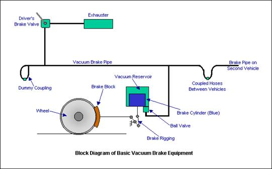
Parts of a Vacuum Braking System
The different parts of a Vacuum Braking System are as below:-
DRIVER’S BRAKE VALVE
The means by which the driver controls the brake. The brake valve will have (at least) the following positions: "Release", "Running", "Lap" and "Brake On". There may also be a "Neutral" or "Shut Down" position, which locks the valve out of use. The "Release" position connects the exhauster to the brake pipe and switches the exhauster to full speed. This raises the vacuum in the brake pipe as quickly as possible to get a release.
EXHAUSTER
A two-speed rotary machine fitted to a train to evacuate the atmospheric pressure from the brake pipe, reservoirs and brake cylinders to effect a brake release. It is usually controlled from the driver's brake valve, being switched in at full speed to get a brake release or at slow speed to maintain the vacuum at its release level while the train is running. Exhausters are normally driven off an electric motor but they can be run directly from a diesel engine.
BRAKE PIPE
The vacuum-carrying pipe running the length of the train, which transmits the variations in pressure required to control the brake. It is connected between vehicles by flexible hoses, which can be uncoupled to allow vehicles to be separated. The use of the vacuum system makes the brake "fail safe", i.e. the loss of vacuum in the brake pipe will cause the brake to apply.
DUMMY COUPLING
At the ends of each vehicle, a dummy coupling point is provided to allow the ends of the brake pipe hoses to be sealed when the vehicle is uncoupled. The sealed dummy couplings prevent the vacuum being lost from the brake pipe.
COUPLED HOSES
The brake pipe is carried between adjacent vehicles through flexible hoses. The hoses can be sealed at the outer ends of the train by connecting them to dummy couplings.
BRAKE CYLINDER
Each vehicle has at least one brake cylinder. Sometimes two or more are provided. The movement of the piston contained inside the cylinder operates the brakes through links called "rigging". The rigging applies the blocks to the wheels. The piston inside the brake cylinder moves in accordance with the change in vacuum pressure in the brake pipe. Loss of vacuum applies the brakes, restoration of the vacuum releases the brakes.
VACUUM RESERVOIR
The operation of the vacuum brake relies on the difference in pressure between one side of the brake cylinder piston and the other. In order to ensure there is always a source of vacuum available to operate the brake, a vacuum reservoir is provided on, or connected to the upper side of the piston. In the simplest version of the brake, shown above, the brake cylinder is integral with the vacuum reservoir. Some versions of the brake have a separate reservoir and a piped connection to the upper side of the piston.
BRAKE BLOCK
This is the friction material which is pressed against the surface of the wheel tread by the upward movement of the brake cylinder piston. Often made of cast iron or some composition material, brake blocks are the main source of wear in the brake system and require regular inspection to see that they are changed when required.
BRAKE RIGGING
This is the system by which the movement of the brake cylinder piston transmits pressure to the brake blocks on each wheel. Rigging can often be complex, especially under a passenger car with two blocks to each wheel, making a total of sixteen. Rigging requires careful adjustment to ensure all the blocks operated from one cylinder provide an even rate of application to each wheel. If you change one block, you have to check and adjust all the blocks on that axle.
BALL VALVE
The ball valve is needed to ensure that the vacuum in the vacuum reservoir is maintained at the required level, i.e. the same as the brake pipe, during brake release but that the connection to the brake pipe is closed during a brake application. It is necessary to close the connection as soon as the brake pipe vacuum is reduced so that a difference in pressure is created between the upper and lower sides of the brake cylinder piston. See the next paragraph - Operation on Each Vehicle
Driver’s Brake Valve
The means by which the driver controls the brake. The brake valve will have (at least) the following positions: "Release", "Running", "Lap" and "Brake On". There may also be a "Neutral" or "Shut Down" position, which locks the valve out of use. The "Release" position connects the exhauster to the brake pipe and switches the exhauster to full speed. This raises the vacuum in the brake pipe as quickly as possible to get a release.
In the "Running" position, the exhauster keeps running but at its slow speed. This ensures that the vacuum is maintained against any small leaks or losses in the brake pipe, connections and hoses.
"Lap" is used to shut off the connection between the exhauster and the brake pipe to close off the connection to atmosphere after a brake application has been made. It can be used to provide a partial release as well as a partial application, something not possible with the original forms of air brake.
"Brake On" closes off the connection to the exhauster and opens the brake pipe to atmosphere. The vacuum is reduced as air rushes in.
Some brake valves were fitted with an "Emergency" position. Its operation was the same as the "Brake On" position, except that the opening to atmosphere was larger to give a quicker application.
Related Seminar Topics
- Nitro Shock Absorbers
- Paper Battery
- Pistonless Pump
- Pollution Less Engine
- Re-entry-of-Space-Vehicle
- Robotic Car
- Scramjet Engine
- Self Healing Robots
- Sensotronic Brake Control
