Published on Jun 05, 2023
Variable Valve Timing In I.C
VALVE TIMING (VT) is one of the most important aspects of consideration in the design of an automobile engine. Simply defined, it is the timing, or regulation of the opening and closing of the valves. In simpler terms, it is the way an engine ‘breathes’.
In an I.C.engine, usually the inlet valves open a few degrees (of crank angle) prior to TDC, and close after BDC. Similarly, the exhaust valves open a few degrees before BDC and close a few degrees after TDC. This is done to maximise:
Intake of air/air-fuel mixture; and
Scavenging, i.e. the exhaust of burnt gases.
Until recently, most engines around the world utilised ordinary or static VT, where the parameters of valve opening, lift, and closing (VO, VL and VC) were fixed. This was satisfactory at normal engine speeds, but posed problems at high and low speeds. Since the VT did not vary with speed, the additional requirements that arose at the extreme speeds could not be met with static VT. For example, at high speeds, the engine requires greater amounts of air. This implies that the IV should remain open for a longer period of time. This, though beneficial at high speeds, would be a menace at low speeds as it may lead to exhaust of unburnt fuel, which results in fuel wastage, increased emissions and lower performance
Valve timing is the regulation of the points in the combustion cycle, at which the valves are set to open and close. Since the valves require a finite period of time in which to open or close without abruptness, a slight lead-time is always necessary for proper operation. The design of the valve-operating cam provides for the smooth transition from one position to the other, while the cam setting determines the timing of the valve.
In a typical four-stroke engine, the inlet valve is set to open before TDC (top dead centre), towards the end of the exhaust stroke and close after BDC (bottom dead centre), at the start of the compression stroke
.
INTRODUCTION
Around the early 1990s, Variable Valve Timing [VVT] started to become popular on gasoline passenger cars. Using this technique, engine manufacturers were enabled to control the extent and duration for which the poppet valves were open. In addition, the opening and closing of the valve could also be varied depending on the crank angle. In the absence of Variable Valve Timing technology, engineers used to choose the best `compromise’ timing. For example, a van may adopt less overlapping for the benefits of low-speed output. A racing engine may adopt considerable overlapping for high-speed power. An ordinary sedan may adopt valve timing optimise for mid-rev so that both the low-speed drivability and high-speed output will not be sacrificed too much. No matter which one, the result is just optimised for a particular speed.
While the intake valve should open, theoretically at TDC, most engines utilise an intake valve opening, which is timed to occur a few degrees prior to the arrival of the piston at TDC on the exhaust stroke. This is because by the time the valve becomes fully open, the piston would have travelled considerably down the bore, and since the valve would have to be fully closed before BDC, the actual time the valve would be fully open would be minimal.
Additionally, the inertia of the incoming mixture plays a big role. Keeping the inlet valve open after BDC forces more mixture to pack into the cylinder, in spite of the fact that the piston is moving upwards
TYPES OF VVT MECHANISMS
Cam-Phasing VVT
Cam-phasing VVT is at present, the simplest, cheapest and most commonly used mechanism. However, its performance gain is also the least.
Basically, shifting the phase angle of camshafts varies the valve timing. For example, at high speeds, the inlet camshaft will be rotated in advance by 30° so as to enable earlier intake. This movement is controlled by an engine management system according to need, and actuated by hydraulic valve gears.
Lift v angle diagram (Toyota VVT-i)
Cam-phasing VVT cannot vary the duration of valve opening. It only allows earlier or later valve opening. Earlier opening results in earlier close. It cannot vary the valve lift. However, cam-phasing VVT is the simplest and cheapest form of VVT because each camshaft needs only one hydraulic phasing actuator, unlike other systems that employ individual mechanism for every cylinder.
Better systems have continuous variable shifting, say, any arbitrary value between 0° and 30°, depending on r.p.m. This provides the most suitable valve timing at any speed, thus greatly enhancing engine flexibility. Moreover, the transition is so smooth that it is hardly noticeable.
Lift v angle diagram (BMW Double Vanos)
The end of camshaft incorporates a gear thread. The thread is coupled by a cap, which can move towards and away from the camshaft. Because the gear thread is not in parallel to the axis of camshaft, phase angle will shift forward if the cap is pushed towards the camshaft. Similarly, pulling the cap away from the camshaft results in shifting the phase angle backward. The hydraulic pressure determines push or pull. There are two chambers right beside the cap and they are filled with liquid. A thin piston separates these two chambers, the former attaches rigidly to the cap. Liquid enter the chambers via electromagnetic valves, which controls the hydraulic pressure acting on which chambers. For instance, if the engine management system signals the valve at the green chamber open, then hydraulic pressure acts on the thin piston and push the latter, accompany with the cap, towards the camshaft, thus shift the phase angle forward. Continuous variation in timing is easily implemented by positioning the cap at a suitable distance according to engine speed.
Cam-Changing VVT
Honda pioneered road car-used VVT in the late 80s by launching its famous VTEC system (Valve Timing Electronic Control). First appeared in Civic, CRX and NS-X, and then became standard in most models.
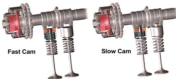
Two sets of cams having different shapes to enable different timing and lift. One set operates during normal speed, say, below 4,500 r.p.m.. The other set substitutes at higher speeds. Such layout does not allow continuous change of timing, therefore the engine performs modestly below 4,500 r.p.m. but above that it will suddenly transform into a wild animal
VVT-i (Variable Valve Timing–intelligent)
Toyota originally introduced the VVT-i (Variable Valve Timing - intelligent) as a revolutionary design that increases engine torque and output while addressing environmental issues. By adjusting the intake valve opening timing according to the engine speed, more oxygen is supplied through the air intake valve as more fuel is injected into the combustion chamber. Power and torque is maximized due to larger scale combustion. This optimised fuel to air ratio ensures the air-fuel mixture is combusted more thoroughly
Cam-Phasing and Cam-Changing VVT
Combining cam-changing VVT and cam-phasing VVT could satisfy the requirement of both top-end power and flexibility throughout the whole rev range, but it is inevitably more complex. Presently, only Toyota and Porsche have such designs. However more and more sports cars are believed to adopt this VVT mechanism in the future.
VTEC (Variable Valve Timing and Lift Electronic Control)
VTEC (Variable Valve Timing and Lift Electronic Control) is an electronic and mechanical system in some Honda engines that allows the engine to have multiple camshafts. VTEC engines have an extra intake cam with its own rocker, which follows this cam. As the engine moves into different r.p.m. ranges, the engine's computer can activate alternate lobes on the camshaft and change the cam's timing. The profile on this cam keeps the intake valve open longer than the other cam profile. At low engine speeds, this rocker is not connected to any valves. At high engine speeds, a piston locks the extra rocker to the two rockers that control the two intake valves. In this way, the engine gets the best features of low-speed and high-speed camshafts in the same engine.
Rover's unique VVC system
Rover introduced its own system calls VVC (Variable Valve Control) in MGF in 1995. Many experts regard it as the best VVT considering its all-round ability - unlike cam-changing VVT, it provides continuously variable timing, thus improve low to medium rev torque delivery; and unlike cam-phasing VVT, it can lengthen the duration of valves opening (and continuously), thus boost power.
Basically, VVC employs an eccentric rotating disc to drive the inlet valves of every two cylinder. Since eccentric shape creates non-linear rotation, valves opening period can be varied.
VVC has one draw back: since every individual mechanism serves 2 adjacent cylinders, a V6 engine needs 4 such mechanisms, and that's not cheap. V8 also needs 4 such mechanism. V12 is impossible to be fitted, since there is insufficient space to fit the eccentric disc and drive gears between cylinders
Related Seminar Topics
- Nitro Shock Absorbers
- Paper Battery
- Pistonless Pump
- Pollution Less Engine
- Re-entry-of-Space-Vehicle
- Robotic Car
- Scramjet Engine
- Self Healing Robots
- Sensotronic Brake Control
